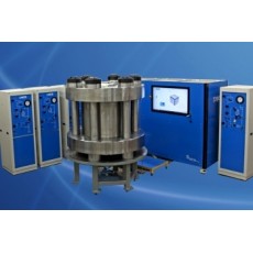
RPS-600 Poly-Axial (True Triaxial) Rock Testing System
The RPS-600 is designed to test cubical specimens 12" × 12" × 12" and have the capability of applying orthogonal stresses in each of the three principal directions. The maximum major principal stress is 15,000 psi. This system provides independent control of all three principal stresses.
Hydraulic pressures to fracture rock specimens can be applied at the center of the cubical specimen while controlling all three principal stresses. A second pressure port is also provided to measure specimen pore pressures.
Ultrasonic velocity can be measure in any orthogonal direction as well as acoustic emissions while applying test stresses and hydraulic fracturing pressures. Three- dimensional event location software is also included.
The RPS-600 has 6 actuator blocks (one on each principal stress direction) with 9 hydraulic cylinders each for a total of 56 cylinders. The hydraulic cylinders are actuated with up to 20,000 psi hydraulic pressure generated from three servo-controlled intensifiers (one for each axis). The maximum total force for each actuator block is approximately 1,500,000 lbs. The maximum stress on each direction is dependent upon the specimen size.
The RPS-600 includes a pressure vessel and a manually controlled intensifier capable of applying hydrostatic stresses up to 10,000 psi using confining pressure alone. For "true triaxial" tests where all principal stresses are different from each other, the maximum major principal stress is 15,000 psi for a cubical specimen 12" × 12" × 12". Higher stresses can be attained by reducing the specimen size. Each row of cylinders is plumbed independently, allowing to use additional pressure intensifiers for applying stress gradient on any direction.
Hydrostatic stresses are applied, much like in a standard triaxial cell, using oil as confining media. The confining pressure minimizes the stress concentration at the specimen edges where the loading plates may intersect. Note that in order to avoid overlapping of the loading plates at the edges of each specimen face; the loading plates only cover an 11.5" × 11.5" area leaving a 1/4” unloaded strip on each specimen edge. The confining pressure also provides the means to seal the pore/hydraulic fracturing pressures. In addition, confining fluid is necessary to operate the RPS-600 at high temperatures up to 200 °C.
Different stress paths and stress states can be readily programmed within the design limits. All three principal stresses are servo controlled with the capability of applying any stress path within the maximum stress values and stress differences as listed in Table 1.
Additional capabilities are the ability to measure acoustic emissions as well as ultrasonic wave velocities through sensors located at different locations on the cubical specimen. The system includes 32 AE sensors for monitoring acoustic emissions in the test specimen during the loading/unloading as well as the hydraulic fracturing stages. 3-dimensional event location software is provided. Also provided is an ultrasonic pulser to measure specimen wave velocity between any two AE sensors.
The proposed location of the AE sensors is shown in figure 4. There are 6 AE sensors on the specimen sides where a pore/hydraulic fracturing port are located (North and South faces shown in figure 4) and only 5 AE sensors in the each reminding face. Note that this configuration can be modified in many different ways by rearranging the loading plates.
A computer controlled pressure panel is included to operate the RPS-600 Poly-Axial including one pore pressure and one hydraulic fracturing port. Hydraulic
fracturing pressures of up to 20,000 psi can applied at the center of the cubical specimen through a perforated pipe placed in a pre-drilled borehole and
sealed at the loading plate. In addition, a second port, similar to the hydraulic fracturing port, is also provided to measure pore pressures at a predetermined
location. The pressure panel includes automatic valves to switch the pressure intensifier between these ports in order to first saturate the specimen from the
pore pressure port and then apply a fracturing pressure to the center port.
Four servo-controlled pressure intensifiers rated for 20,000 psi are included as well as one manually controlled intensifier rated to 10,000 psi. Three servocontrolled intensifiers are used for the control of the principal stresses. The fourth servo-controlled pressure intensifier is intended for the hydraulic
fracturing pressure. The manually operated pressure intensifier is intended for pressurizing the vessel. Additional pressure intensifiers can be used to Different configurations from the recommended above are also possible requiring only selecting a different test program and redirecting the pressure lines in the
pressure panel.
A heating system capable of controlling the specimen temperature at up to 200 C is included. Test temperatures from room temperature and up to the maximum rated temperature can be programmed and controlled through the GCTS software including the capability to specify final test temperature as well as
heating rates.
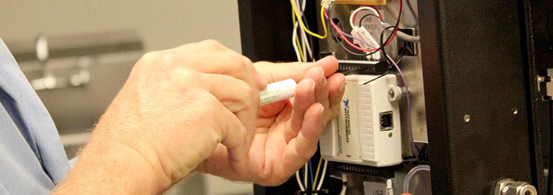
The RPS-600 is operated through a fully digital electronic controller with 24 bit resolution A/D signal conditioner and sensor input readout for up to 14 sensors. A remote monitoring device is also provided to monitor test conditions via internet from anywhere.
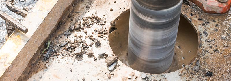
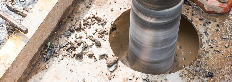
Hydraulic fracturing pressures are applied through a ¼ inch tube placed into the specimen at the center. A ½ inch hole has to be pre-drilled to place the steel ¼” tube and grouting it. An o-ring is glued to the steel tube at the depth where the grouting is required. The hydraulic fracturing pressure is sealed with an o-ring at the loading plate. A port on the side of the loading plate is connected through the cell base to a pressure intensifier.
A second pressure port, similar to the hydraulic fracturing port can be installed on a different loading plate and at a different specimen location. This second pore pressure port location is predetermined at the time the special loading plate is manufactured. GCTS propose to locate the second pore pressure port
4 inches from the loading plate edge. Loading plates with different port configurations can be ordered from GCTS any time as loading plates can easily be
replaced.
Features
- Test cubical 12" × 12" × 12" (300 × 300 by 300 mm) size rock specimens, larger sizes available
- Perform Poly-axial (true triaxial) tests
- Independent control of s1, s2, s3 (where s1?s2?s3) or e1, e2, e3 or a combination of stress or strain control for each axis
- Measures strains in all three orthogonal directions
- Pore pressure control up to 140 MPa
- Ultrasonic sensors to measure P and S wave velocities under different stress states
- Hydraulic fracturing platens available to perform wellbore stability tests
- Acoustic Emission measurements
- Temperature control up to 200 °C
- Systems built to customer specifications

